As a key connector in plastic pipe systems, eccentric reducer HDPE plays an irreplaceable role in municipal drainage, industrial fluid transportation, and mine tailings treatment. Compared with concentric reducers, eccentric design solves a series of technical problems in pipe system installation through its unique structural characteristics. This article will deeply explore the structural characteristics, manufacturing process, selection calculation, installation method, and special application scenarios of HDPE eccentric reducers, providing systematic professional technical references for engineering designers and construction technicians.
Eccentric reducer HDPE basic theory
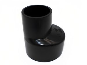
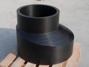
1. Basic structure and type classification
HDPE eccentric reducer can be divided into three types according to the eccentric structure:
Flat on Top: The top of the large diameter end and the small diameter end are kept horizontal, and the bottom is a diagonal transition
Typical application: Prevent gas accumulation at the suction end of the pump
Size range: DN50-DN1200
Transition angle standard: usually 15°-30°
Flat on Bottom: The bottom of the large diameter end and the small diameter end are kept horizontal, and the top is a diagonal transition
Typical application: Drainage pipes maintain bottom slope continuity
Special design: Inspection ports or cleaning ports can be integrated
Hydraulic characteristics: Reduce the risk of sediment accumulation
Side eccentric: One side is aligned in a straight line, and the other side is a diagonal transition
Special working conditions: Pipeline layout in confined space
Installation advantage: Easy to connect with existing pipeline systems
Pressure level: usually PN6-PN16
2. Material properties and standard specifications
The material properties of HDPE eccentric reducers directly affect their service life:
Raw material grade: PE80/PE100 resin melt flow rate (MFR) is controlled at 0.2-0.4g/10min (190℃/5kg)
Long-term performance: 20℃/50 years minimum required strength (MRS) reaches 8-10MPa
Chemical resistance: Resistant to most chemical media with a pH range of 2-12
Industry standards:
ISO 4427: Polyethylene piping system standard
GB/T 13663.2: Polyethylene pipe standard for water supply
ASTM F3354: Polyethylene reducer standard specification
Manufacturing process and technical parameters
1. Extrusion molding process
The manufacturing of high-quality HDPE eccentric reducer involves precision control:
Mold design: Three-dimensional parametric modeling is used, and the radius of curvature in the transition zone is ≥1.5 times the large end diameter
Temperature control: Barrel temperature is controlled in sections (180-220℃), and the die temperature fluctuates by ±2℃
Extrusion pressure: Maintain 15-25MPa to ensure melt density
Cooling and shaping: Graded water cooling system (80℃→40℃→25℃), and the cooling rate is controlled at 15℃/min
2. Key size parameters
DN200×150 eccentric reducer typical size requirements:
| Parameter | Standard Value | Tolerance Range |
| Large End Outer Diameter | 200.0 mm | +0.4 / -0.2 mm |
| Small End Outer Diameter | 150.0 mm | +0.3 / -0.2 mm |
| Total Length | 300 mm | ±5 mm |
| Wall Thickness (Large End) | 9.1 mm | +0.8 / -0.5 mm |
| Eccentricity | 25 mm | ±1 mm |
| Transition Zone Angle | 22.5° | ±1° |
3. Key points of quality inspection
Test items that must be carried out before leaving the factory:
Dimension inspection: full-size measurement using a laser scanner, 100% inspection of key dimensions
Pressure test: no leakage after maintaining pressure for 1 hour at 2.5 times the nominal pressure (PN)
Roundness inspection: ovality of any section ≤3% of the nominal diameter
Welding quality: ultrasonic inspection of the integrity of the fusion line in the transition zone
Appearance inspection: no scratches, bubbles or other defects on the surface, uniform color
Engineering design and selection calculation
1. Key points of hydraulic calculation
The influence of eccentric reducer on hydraulic characteristics of the system:
Local resistance coefficient: ξ=0.1×(1-β²)², β is the diameter ratio (d/D)
DN300→DN200: ξ≈0.13 (pressure drop 0.0065MPa at flow rate 1m/s)
Sudden change of flow rate: small end flow rate v₂=v₁×(D/d)²
It is necessary to check v₂≤3m/s (water supply) or 5m/s (drainage)
Cavitation prevention: The pump suction end adopts top flush type, NPSHa≥1.3NPSHr
2. Structural design criteria
Design principles of pressure piping system:
Wall thickness calculation: according to ISO 12162 standard, t=PD/(2S+0.8P)
Where S=8MPa(PE100, 20℃/50 years)
Consider 1.25 times safety factor
Transition zone optimization:
Length L≥(D-d)/tanθ, θ≤30°
Radius of curvature R≥0.5D
Reinforced design:
Enhanced rib structure is used for PN16 and above
Back support ring is added when flange connection is integrated
3. Selection decision process
Scientific selection steps and methods:
Working condition analysis: Determine the medium, temperature, pressure, and flow parameters
Type selection: Determine the eccentric form according to functional requirements
Size determination: Determine the diameter ratio through hydraulic calculation
Pressure level: Consider the water hammer effect and reserve 30% margin
Connection method: butt welding, flange connection or electric fusion connection
Special requirements: Additional functions such as anti-UV, conductivity, anti-static, etc.
Installation and construction technical specifications
1. Welding connection process
Key points of electric fusion connection operation:
Pretreatment:
Scrape the oxide layer (depth 0.1-0.2mm)
Clean the connection surface with alcohol
Check the resistance value of the electric fuse (usually 40-60Ω)
Alignment and fixation:
Use a special clamp to maintain the eccentricity tolerance ±1mm
Check the levelness of the flush side (error ≤1mm/m)
Welding parameters:
Voltage 39.5±0.5V (DN200)
Welding time is set according to the QR code of the pipe fitting
Cooling time ≥1.5 times the welding time
Quality inspection:
Observation hole protrusion height ≥3mm
No coking of the electric fusion sleeve
Mark and record welding parameters
2. Flange connection installation
Installation steps of flanged eccentric reducer:
Pre-assembly inspection:
Parallelism of flange surface ≤0.5mm
100% centering of bolt hole
Use PTFE gasket (thickness 3-5mm)
Graded tightening:
Tighten three times in cross order
Final torque value: M20 bolt 120-150N·m
Retighten after 24 hours
Eccentricity correction:
Use laser level to calibrate the flush side
Allowable deviation: ±2mm/meter
3. Installation under special working conditions
Underground installation:
Ditch bottom flatness: ±10mm/2m
Sand cushion thickness: ≥150mm
Backfill soil compaction: ≥90% standard Procter density
Overhead pipeline installation:
Span between brackets: 1.5×standard pipe spacing
Thermal compensation design: set a Z-type compensator every 30m
Ultraviolet protection measures: apply special protective coating

Typical application case analysis
1. Municipal drainage system
A city’s DN800 rainwater pipe network renovation project:
Problem: Pipe settlement at the inspection well leads to water accumulation on the reverse slope
Solution: Use bottom flush eccentric reducer (FOB)
Large end DN800→small end DN600
Eccentric distance 100mm to compensate for elevation difference
Integrated stainless steel anti-corrosion short pipe joint
Effect: Restore the design slope by 0.5%, and increase the drainage capacity by 30%
2. Industrial pump station system
Chemical plant acid delivery pump inlet renovation:
Original problem: Concentric reducer causes cavitation, and the impeller life is only 3 months
Renovation plan: Top flush electric fusion eccentric reducer
Material: PE100 RC stress cracking resistance grade
Size: DN250→DN200
Integrated vent valve and pressure monitoring port
Operation effect: Cavitation noise is reduced by 15dB, and pump efficiency is increased by 8%
3. Mine tailings transportation
High-concentration slurry pipeline system:
Challenge: 70% solid content slurry is easy to settle
Innovative design: Lateral eccentric reducer + wear-resistant lining
45° eccentric angle promotes solid particle flow
Inner lining 3mm thick polyurethane wear-resistant layer (hardness Shore D75)
Flange connection with quick disassembly structure
Service life: extended to 18,000 hours compared with traditional design
Maintenance and troubleshooting
1. Common fault diagnosis
Weld cracking:
Phenomenon: Circumferential cracks in the transition zone
Cause: Welding cooling too fast (<2℃/min)
Solution: Infrared preheating to 60℃ and then slow cooling
Flange leakage:
Phenomenon: Medium seepage at the bolt
Cause: Thermal expansion causes bolt loosening
Handling: Use spring washers instead and tighten regularly
Inner wall wear:
Phenomenon: Flat side wall thickness thinning>10%
Cause: Washing with solid particle-containing medium
Countermeasure: Rotate 180° or install wear-resistant bushing
2. Preventive maintenance plan
Quarterly inspection:
Flange bolt torque detection (deviation ≤ 15%)
Visual inspection of surface cracks (using a 10x magnifying glass)
Displacement measurement of joints (allowable value ± 5mm)
Annual maintenance:
Ultrasonic thickness measurement (focus on monitoring the transition zone)
Infrared thermal imaging to check temperature distribution
Replacement of seals (service life exceeds 5 years)
Emergency treatment:
Temporary fixture: stainless steel emergency repair half joint
Quick repair: fiber reinforced composite material coating
Pressure plugging: special PE pipe plugger
Eccentric reducer HDPE is an important component in modern pipeline engineering. Its reasonable selection and correct installation are directly related to the reliability and service life of the entire pipeline system. It is recommended that when applying it in engineering: (1) Pay attention to the preliminary design calculation, especially the analysis of hydraulic characteristics and structural stress; (2) Strictly control the manufacturing quality and give priority to products certified by ISO 9001 and ISO 4427; (3) Standardize the installation process, especially the control of welding process parameters; (4) Establish a complete maintenance file and implement condition-based preventive maintenance. With the development of new materials and new processes, innovative technologies such as intelligent monitoring and self-repairing will bring broader application prospects for HDPE eccentric reducers.